8237 Direct Memory Access (DMA) Controller
Basic DMA operation
- The direct memory access (DMA) I/O technique provides direct access to the memory while the microprocessor is temporarily disabled.
- A DMA controller temporarily borrows the address bus, data bus, and control bus from the microprocessor and transfers the data bytes directly between an I/O port and a series of memory locations.
- The DMA transfer is also used to do high-speed memory-to-memory transfers.
- Two control signals are used to request and acknowledge aDMA transfer in the microprocessor-based system.
- The HOLD signal is a bus request signal which asks the microprocessor to release control of the buses after the current bus cycle.
- The HLDA signal is a bus grant signal which indicates that the microprocessor has indeed released control of its buses by placing the buses at their high-impedance states.
- The HOLD input has a higher priority than the INTR or NMI interrupt inputs.
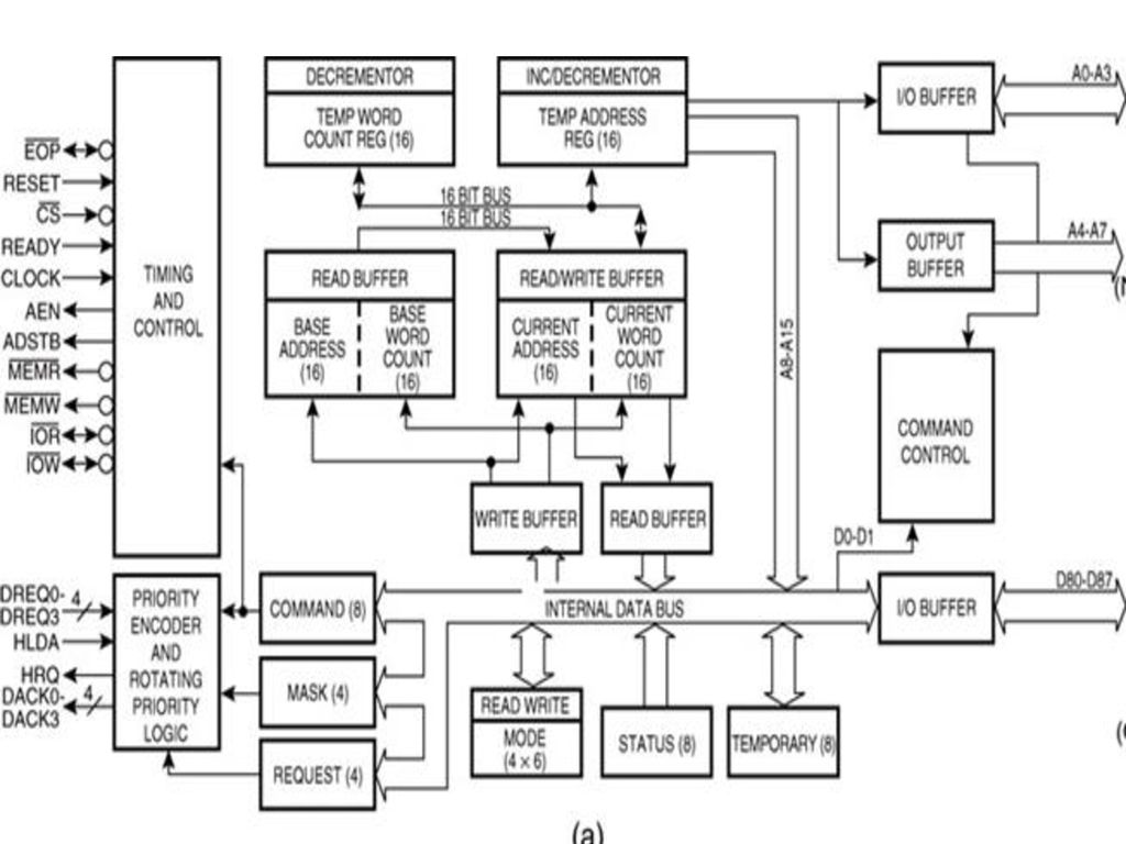
The 8237 DMA controller
- The 8237 DMA controller supplies the memory and I/O with control signals and memory address information during the DMA transfer.
- The 8237 is a four-channel device that is compatible to the 8086/8088 microprocessors and can be expanded to include any number of DMA channel inputs.
- The 8237 is capable of DMA transfers at rates of up to 1.6M bytes per second.
- Each channel is capable of addressing a full 64K-byte section of memory and can transfer up to 64K bytes with a single programming.


Some important signal pins:
- DREQi (DMA request): Used to request a DMA transfer for a particular DMA channel.
- DACKi (DMA channel acknowledge): Acknowledges a channel DMA request from a device.
- HRQ (Hold request): Requests a DMA transfer.
- HLDA (Hold acknowledge) signals the 8237 that the microprocessor has relinquished control of the address, data and control buses.
- AEN (Address enable): Enables the DMA address latch connected to the 8237 and disable any buffers in the system connected to the microprocessor. (Use to take the control of the address bus from the microprocessor)
- ADSTB (Address strobe): Functions as ALE to latch address during the DMA transfer.
- EOP (End of process): Signals the end of the DMA process.
- IOR (I/O read): Used as an input strobe to read data from the 8237 during programming and used as an output strobe to read data from the port during a DMA write cycle.• IOW (I/O write): Used as an input strobe to write data to the 8237 during programming and used as an output strobe to write data to the port during a DMA read cycle.
- MEMW (Memory write): Used as an output to cause memory to write data during a DMA write cycle.
- MEMR (Memory read): Used as an output to cause memory to read data during a DMA read cycle.
Internal registers
- The current address register (CAR) is used to hold the 16-bit memory address used for the DMA transfer.
- The current word count register (CWCR) programs a channel for the number of bytes (up to 64K) transferred during a DMA action.
- The base address (BA) and base word count (BWC) registers are used when auto-initialization is selected for a channel. In this mode, their contents will be reloaded to the CAR and CWCR after the DMA action is completed.
- Each channel has its own CAR, CWCR, BA and BWC.
- The command register (CR) programs the operation of the 8237 DMA controller
- The mode register (MR) programs the mode of operation for a channel.
- The request register (RR) is used to request a DMA transfer via software, which is very useful in memory-to-memory transfers.
- The mask register set/reset (MRSR) sets or clears the channel mask to disable or enable particular DMA channels.
- The mask register (MSR) clears or sets all of the masks with one command instead of individual channels as with the MRSR.
- The status register (SR) shows the status of each DMA channel


Comments
Post a Comment