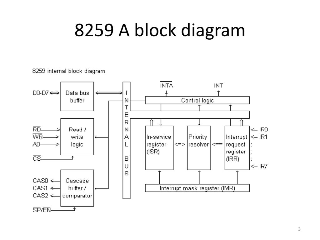
8259A PROGRAMMABLE INTERRUPT CONTROLLER
- The Intel 8259A Programmable Interrupt Controller handles up to eight vectored priority interrupts for the CPU. It is cascadable for up to 64 vectored priority interrupts without additional circuitry. It is packaged in a 28-pin DIP, uses NMOS technology and requires a single a5V supply. Circuitry is static, requiring no clock input.
- The 8259A is designed to minimize the software and real time overhead in handling multi-level priority interrupts. It has several modes, permitting optimization for a variety of system requirements.
- The 8259A is fully upward compatible with the Intel 8259. Software originally written for the 8259 will operate the 8259A in all 8259 equivalent modes (MCS-80/85, Non-Buffered, Edge Triggered
Table: Pin Description
|
Symbol |
Pin No. |
Type |
Name and Function |
|
Vcc |
28 |
I |
Supply: +5V Supply. |
|
GND |
14 |
I |
Ground |
|
CS” |
1 |
I |
Chip Select: A low on this pin enables RD and WR communication between the CPU and the 8259A. INTA functions are independent of CS |
|
WR” |
2 |
I |
Write: A low on this pin when CS is low enables the 8259A to accept command words from the CPU. |
|
RD” |
3 |
I |
Read: A low on this pin when CS is low enables the 8259A to release status onto the data bus for the CPU. |
|
D7-D0 |
4-11 |
I/O |
Bidirectional Data Bus: Control, status and interrupt-vector information is transferred via this bus. |
|
CAS0-CAS2 |
12,13,15 |
I/O |
Cascade Lines: The CAS lines form a private 8259A bus to control a multiple 8259A structure. These pins are outputs for a master 8259A and inputs for a slave 8259A. |
|
SP”/EN” |
16 |
I/O |
Slave Program/Enable Buffer: This is a dual function pin. When in the Buffered Mode it can be used as an output to control buffer transceivers (EN). When not in the buffered mode it is used as an input to designate a master (SP e 1) or slave (SP e 0). |
|
INT |
17 |
O |
Interrupt: This pin goes high whenever a valid interrupt request is asserted. It is used to interrupt the CPU, thus it is connected to the CPU’s interrupt pin. |
|
IR0-IR7 |
18-25 |
I |
Interrupt Requests: Asynchronous inputs. An interrupt request is executed by raising an IR input (low to high), and holding it high until it is acknowledged (Edge-Triggered Mode), or just by a high level on an IR input (Level-Triggered Mode). |
|
INTA” |
26 |
I |
Interrupt Acknowledge: This pin is used to enable 8259A interrupt-vector data onto the data bus by a sequence of interrupt acknowledge pulses issued by the CPU. |
|
A0 |
27 |
I |
AO Address Line: This pin acts in conjunction with the CS, WR, and RD pins. It is used by the 8259A to decipher various Command Words the CPU writes and status the CPU wishes to read. It is typically connected to the CPU A0 address line (A1 for 8086, 8088). |


Comments
Post a Comment